前回まで/次回以降の取り組みはこちらから。
Arduinoで照度を測る
照度を測るにもいろいろなセンサがあります。
よく用いられるのはCdSやフォトトランジスタという部品です。
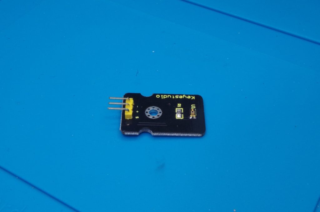
今回はTEMT6000というフォトトランジスタを利用し「環境光センサ」を使ってみます。
光の感度特性が人間の目の特性に似ていて、明るさを表す単位の「lx」(ルクス)単位で出力ができるということのようなので使ってみます。
前々回に紹介したパーツキットには入っていませんが、同じ部品を使ったモジュールが売られています。
今回は別のパーツキットに入っていた手持ちのものを利用しました。
もちろん、CdSや通常のフォトトランジスタでも構いません。
Arduinoに接続する
今回は使用する基板には動作に必要な抵抗が実装されています。
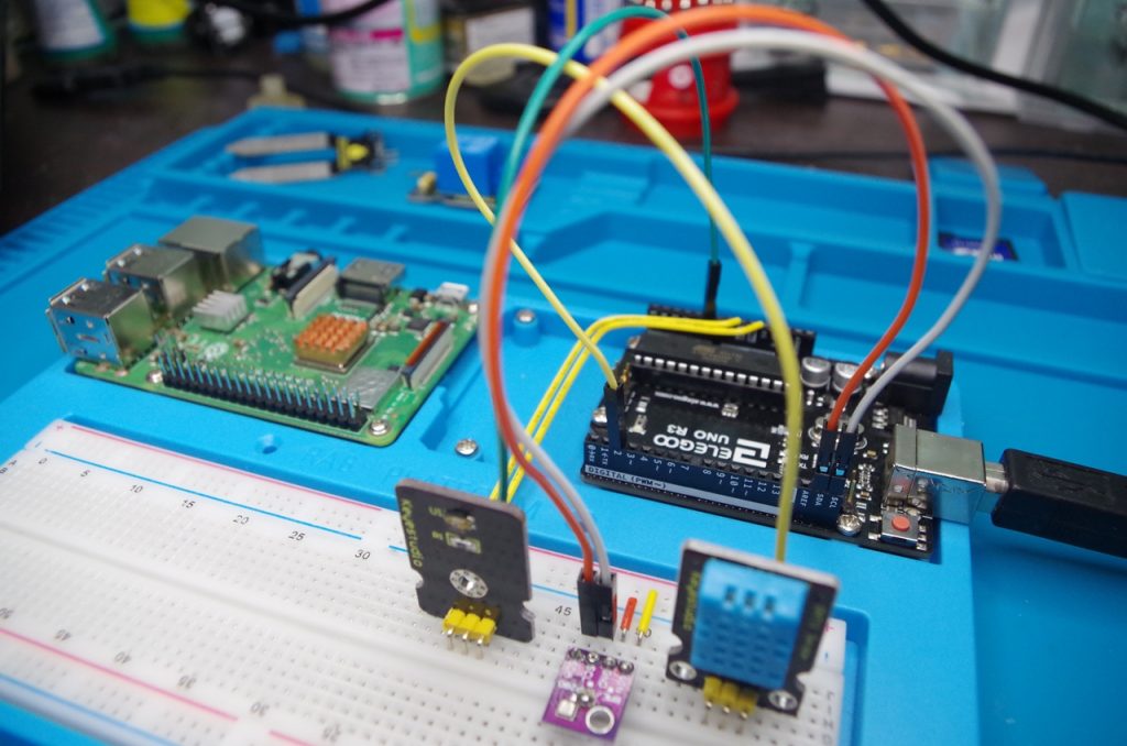
「+」ピンは5V、「ー」ピンはGND、「S」ピンはA0(アナログピンならどこでもよい)にそれぞれ接続します。


(センサの陰でちゃんとつないであります…)
Arduinoで読み取ってみる
今回はライブラリは不要です。
analogReadで読み取ればそのままセンサの出力を読み取ることができます。
ちょうど使えるサンプルスケッチがありますので、それを利用してみましょう。
サンプルスケッチを開く
メニューバー[ファイル]→[スケッチ例]→[03.Analog]からサンプルスケッチ「AnalogInOutSerial.ino」を開いてみます。
1 2 3 4 5 6 7 8 9 10 11 12 13 14 15 16 17 18 19 20 21 22 23 24 25 26 27 28 29 30 31 32 33 34 35 36 37 38 39 40 41 42 43 44 45 46 47 48 49 50 51 52 | /* Analog input, analog output, serial output Reads an analog input pin, maps the result to a range from 0 to 255 and uses the result to set the pulse width modulation (PWM) of an output pin. Also prints the results to the Serial Monitor. The circuit: - potentiometer connected to analog pin 0. Center pin of the potentiometer goes to the analog pin. side pins of the potentiometer go to +5V and ground - LED connected from digital pin 9 to ground created 29 Dec. 2008 modified 9 Apr 2012 by Tom Igoe This example code is in the public domain. http://www.arduino.cc/en/Tutorial/AnalogInOutSerial */ // These constants won't change. They're used to give names to the pins used: const int analogInPin = A0; // Analog input pin that the potentiometer is attached to const int analogOutPin = 9; // Analog output pin that the LED is attached to int sensorValue = 0; // value read from the pot int outputValue = 0; // value output to the PWM (analog out) void setup() { // initialize serial communications at 9600 bps: Serial.begin(9600); } void loop() { // read the analog in value: sensorValue = analogRead(analogInPin); // map it to the range of the analog out: outputValue = map(sensorValue, 0, 1023, 0, 255); // change the analog out value: analogWrite(analogOutPin, outputValue); // print the results to the Serial Monitor: Serial.print("sensor = "); Serial.print(sensorValue); Serial.print("\t output = "); Serial.println(outputValue); // wait 2 milliseconds before the next loop for the analog-to-digital // converter to settle after the last reading: delay(2); } |
今回は書き換えの必要なく、このまま動かすことができます。
動かしてみる
ここまででArduinoに書き込んでみます。
(図が前々回の使いまわしやんけ…)
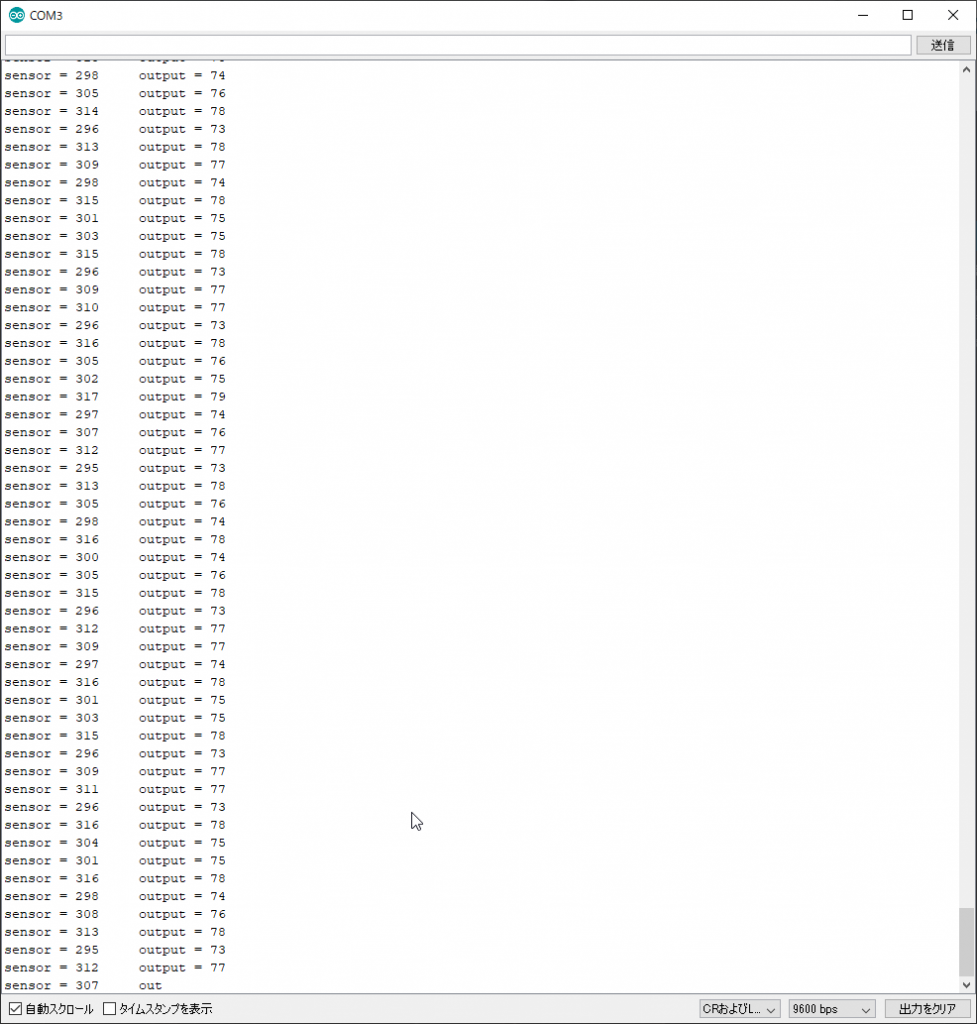
書き込んだら、シリアルモニタを起動します

照度がPCにシリアル通信で返ってきています。
センサに光を当てたり、手などで覆ってみたりすると数値が変化するのが分かります。

照度をlx単位で出力する
TEMT6000のデータシートによると、出力電流と照度はこんな特性になっています。
両対数グラフなので一見ややこしいですが、照度と電流は正比例しています。
電流と照度とを関数で表すと、
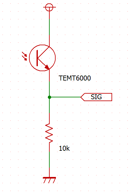
一方、今回のセンサモジュールはこんな回路になっています。
VCCー出力間にセンサ、出力ーGND間に10kΩの抵抗が付いています。
直列接続なので、TEMT6000と10kΩの抵抗には同じだけ電流が流れます。
(実際には10kΩと並列にArduinoのアナログピンの入力抵抗がつながりますが、データシートを見ると入力Z=100MΩとのことなので、そちらに流れ出る電流は十分に小さい(1/1000)ため無視しました。)
オームの法則より、
今回知りたいのは10kΩの両端の電圧で、流れる電流センサが明るさに応じて流す電流と同じです。
つまり、センサモジュールの出力電圧と照度の関係は、
となります。つまり、
という関係になりますので、
ArduinoのanalogReadでは0~5Vの電圧を0~1023の数字で表現しますので、だいたいanalogRaedの読み取り値≒lx単位の照度ととらえてよさそうです。
あさがお観察用スケッチを作る
今回もサンプルスケッチをもとに最終仕様のスケッチを作っていきます。
前回までに作成したスケッチに追加して、一つのスケッチにまとめます。
1 2 3 4 5 6 7 8 9 10 11 12 13 14 15 16 17 18 19 20 21 22 23 24 25 26 27 28 29 30 31 32 33 34 35 36 37 38 39 40 41 42 43 44 45 46 47 48 49 50 51 52 53 54 55 56 57 58 59 60 61 62 63 64 65 66 | // あさがおIoT観察日記 Arduino側プログラム // 2020.05.21 V0.0.1 DHT11による温度・湿度取得(DHT11サンプルスケッチより作成) // V0.0.2 BME280気圧取得(BME280サンプルスケッチより作成) // 2020.05.23 V0.0.3 TEMT6000による照度取得 #include <Adafruit_Sensor.h> #include <DHT.h> #include <DHT_U.h> #define DHTPIN 2 // Digital pin connected to the DHT sensor #define DHTTYPE DHT11 // DHT 11 DHT_Unified dht(DHTPIN, DHTTYPE); #include <Wire.h> #include <SPI.h> #include <Adafruit_BME280.h> #define SEALEVELPRESSURE_HPA (1013.25) Adafruit_BME280 bme; // I2C uint32_t delayMS; int Alt = 120; void setup() { Serial.begin(9600); dht.begin(); delayMS = 1000; bme.begin(0x76); } void loop() { double temp; double temp_0; double humid; double pres; double pres_0; int bright; delay(delayMS); sensors_event_t event; //温度取得 dht.temperature().getEvent(&event); if (!isnan(event.temperature)) { temp = event.temperature; } //湿度取得 dht.humidity().getEvent(&event); if (!isnan(event.relative_humidity)) { humid = event.relative_humidity; } //気圧取得 pres = bme.readPressure() / 100; pres_0 = pres/(pow((1-((0.0065*Alt)/(bme.readTemperature()+0.0065*Alt+273.15))),5.257)); //海面更生 //照度取得 bright = analogRead(0); //シリアル送信 Serial.println(temp); Serial.println(humid); Serial.println(pres); Serial.println(pres_0); Serial.println(bright); } |
照度センサの読み取り値を「bright」というint型の変数に代入し、シリアル通信でPCに送るようにしてみました。
最終的にはシリアル通信でPCではなくRaspberryPiに送って、IoTサービスにデータをアップロードしていく、という流れになります。
最終的にはながーいケーブルで屋外にまで引き回して使いますが、ひとまずブレッドボード上での動作確認はこれでOK。
これで温度・湿度・気圧・照度が測定できるようになりました。
まだまだ続きます。



コメント